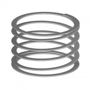
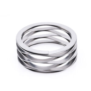
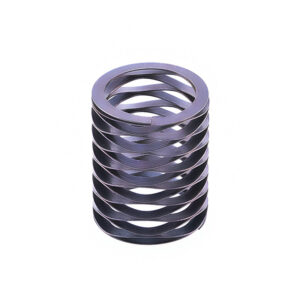
Carbon Stainless Steel Multi-Turn Wave Spring Specification Table 17-7ph Carbon / Stainless Steel
Descrizione:
- Carbon stainless steel Multi-Turn Wave Springs are made of a single filament of round-edged, pre-tempered flat wire from a continuous coil. This results in uniform diameters and wave heights. They replace conventional round wire springs when space is critical, typically occupying only 1/3 to 1/2 of the compressed height space, while providing more deflection with the same load specifications.
- Carbon stainless steel Multi-Turn Wave Spring should be used for all applications requiring tight load deflection specifications where axial space is critical.
- Possiamo produrre molle a disegno, campioni. Se richiedi questi, per favore contatto Me.
Confronto tra molle in acciaio inossidabile e molle in acciaio al carbonio:
1. Materiale la composizione è diversa
The main disadvantage of carbon steel springs is that they are easy to rust, especially when used in high temperature and high humidity environments. When the ambient temperature and humidity are high, stainless steel springs should be used.
2. Diverse tecniche di produzione
Il processo di produzione del materiale in acciaio al carbonio consiste nell'ottenere l'elevata durezza della molla di produzione temprando e temprando il materiale di base con bassa durezza. Questo processo porta a scarsa tenacità del materiale in acciaio al carbonio e inferiore servizio vita. Nelle applicazioni pratiche, ci sarà un'intera primavera. Il fenomeno della frattura, il materiale in acciaio inossidabile è ottenuto dal laminatoio del metallo di base a bassa durezza attraverso più volte per ottenere lo spessore e la durezza richiesti per la produzione di molle, e ottiene anche una buona tenacità, che alla fine porterà a una migliore durata rispetto alle molle in acciaio al carbonio. Allo stesso tempo, le prestazioni sono più stabili.
3. Differenza di prezzo del materiale
Poiché il contenuto di cromo nel materiale della molla in acciaio inossidabile rappresenta 16-18% e il contenuto di nichel rappresenta 6%-8%, il prezzo è anche 2-3 volte più costoso dell'acciaio al carbonio. Per molle della stessa specifica, le molle in acciaio inossidabile saranno più costose delle molle in acciaio al carbonio. Il prezzo sarà circa 2 volte più costoso.
La forza della molla dell'acciaio inossidabile è inferiore a quella della molla in acciaio al carbonio, la durezza della molla in acciaio inossidabile è inferiore a quella del filo di acciaio al carbonio, ma la durata è più lunga; la molla in acciaio al carbonio è più facile da arrugginire rispetto alla molla in acciaio inossidabile e ha requisiti più elevati sull'ambiente di utilizzo.
La sezione materiale della spirale molla ondulata multigiro in acciaio inossidabile al carbonio dovrebbe essere preferibilmente una sezione circolare. I materiali a sezione quadrata e rettangolare hanno una forte capacità portante, una buona resistenza agli urti e possono miniaturizzare la molla, ma la fonte dei materiali è piccola. E il prezzo è alto, salvo esigenze particolari, generalmente cerca di non usare questo materiale. Negli ultimi anni, lo sviluppo della laminazione del filo di acciaio piatto invece del filo di acciaio trapezoidale ha ottenuto buoni risultati.
I materiali per molle che lavorano a temperature elevate richiedono una buona stabilità termica, resistenza al rilassamento o allo scorrimento, resistenza all'ossidazione e resistenza alla corrosione a determinati fluidi.
Specifica:
| Parte n. |
Opera in
Diametro del foro |
Albero di Lears
Diametro |
Carico |
Altezza di lavoro |
Altezza libera |
Onde |
Giri |
Pensiero |
Parete radiale |
Indice di rigidezza |
| mm |
mm |
(N) |
mm |
mm |
mm |
mm |
N/MM |
| LMS20-H1 |
20 |
14 |
100 |
4.24 |
6.32 |
3.5 |
3 |
0.33 |
2.01 |
48.08 |
| LMS20-L1 |
20 |
15 |
35 |
2.72 |
6.32 |
3.5 |
3 |
0.2 |
1.8 |
9.72 |
| LMS20-M1 |
20 |
14 |
70 |
3.05 |
6.32 |
3.5 |
3 |
0.25 |
1.98 |
21.41 |
| LMS20-H2 |
20 |
14 |
100 |
5.66 |
8.43 |
3.5 |
4 |
0.33 |
2.01 |
36.1 |
| LMS20-L2 |
20 |
15 |
35 |
3.61 |
8.43 |
3.5 |
4 |
0.2 |
1.8 |
7.26 |
| LMS20-M2 |
20 |
14 |
70 |
4.06 |
8.43 |
3.5 |
4 |
0.25 |
1.98 |
16.02 |
| LMS20-H3 |
20 |
14 |
100 |
7.06 |
10.54 |
3.5 |
5 |
0.33 |
2.01 |
28.74 |
| LMS20-L3 |
20 |
15 |
35 |
4.52 |
10.54 |
3.5 |
5 |
0.2 |
1.8 |
5.81 |
| LMS20-M3 |
20 |
14 |
70 |
5.08 |
10.54 |
3.5 |
5 |
0.25 |
1.98 |
12.82 |
| LMS20-H4 |
20 |
14 |
100 |
8.48 |
12.65 |
3.5 |
6 |
0.33 |
2.01 |
23.98 |
| LMS20-L4 |
20 |
15 |
35 |
5.41 |
12.65 |
3.5 |
6 |
0.2 |
1.8 |
4.83 |
| LMS20-M4 |
20 |
14 |
70 |
6.27 |
12.65 |
3.5 |
6 |
0.25 |
1.98 |
10.97 |
| LMS20-H5 |
20 |
14 |
100 |
9.91 |
14.76 |
3.5 |
7 |
0.33 |
2.01 |
20.62 |
| LMS20-L5 |
20 |
15 |
35 |
6.32 |
14.76 |
3.5 |
7 |
0.2 |
1.8 |
4.15 |
| LMS20-M5 |
20 |
14 |
70 |
7.32 |
14.76 |
3.5 |
7 |
0.25 |
1.98 |
9.41 |
| LMS20-H6 |
20 |
14 |
100 |
12.73 |
18.97 |
3.5 |
9 |
0.33 |
2.01 |
16.03 |
| LMS20-L6 |
20 |
15 |
35 |
8.13 |
18.97 |
3.5 |
9 |
0.2 |
1.8 |
3.23 |
| LMS20-M6 |
20 |
14 |
70 |
9.17 |
18.97 |
3.5 |
9 |
0.25 |
1.98 |
7.14 |
| LMS20-H7 |
20 |
14 |
100 |
16.97 |
25.3 |
3.5 |
12 |
0.33 |
2.01 |
12 |
| LMS20-L7 |
20 |
15 |
35 |
10.82 |
25.3 |
3.5 |
12 |
0.2 |
1.8 |
2.42 |
| LMS20-M7 |
20 |
14 |
70 |
12.22 |
25.3 |
3.5 |
12 |
0.25 |
1.98 |
5.35 |
| LMS25-H1 |
25 |
19 |
110 |
4.04 |
6.63 |
3.5 |
3 |
0.38 |
2.39 |
42.47 |
| LMS25-L1 |
25 |
19 |
50 |
2.06 |
6.63 |
3.5 |
3 |
0.25 |
2.18 |
10.94 |
| LMS25-M1 |
25 |
19 |
80 |
2.95 |
6.63 |
3.5 |
3 |
0.3 |
2.39 |
21.74 |
| LMS25-H2 |
25 |
19 |
110 |
5.38 |
8.84 |
3.5 |
4 |
0.38 |
2.39 |
31.79 |
| LMS25-L2 |
25 |
19 |
50 |
2.74 |
8.84 |
3.5 |
4 |
0.25 |
2.18 |
8.2 |
| LMS25-M2 |
25 |
19 |
80 |
3.94 |
8.84 |
3.5 |
4 |
0.3 |
2.39 |
16.33 |
| LMS25-H3 |
25 |
19 |
110 |
6.73 |
11.05 |
3.5 |
5 |
0.38 |
2.39 |
25.46 |
| LMS25-L3 |
25 |
19 |
50 |
3.43 |
11.05 |
3.5 |
5 |
0.25 |
2.18 |
6.56 |
| LMS25-M3 |
25 |
19 |
80 |
4.9 |
11.05 |
3.5 |
5 |
0.3 |
2.39 |
13.01 |
| LMS25-H4 |
25 |
19 |
110 |
8.08 |
13.26 |
3.5 |
6 |
0.38 |
2.39 |
21.24 |
| LMS25-L4 |
25 |
19 |
50 |
4.11 |
13.26 |
3.5 |
6 |
0.25 |
2.18 |
|